7 segment LEDs can make projects neat. Instead of normal LEDs, you can now display numbers (and limited letters/symbols). A 7 segment LED is actually 8 leds in a particular shape (7 of them are used to display digits and the eighth is a decimal point).
In the early days (before LCD displays took over) most devices used LEDs for output (calculators, clocks, stoves, ...). You still see them currently, but many things have gone to LCD dispalys of various sizes.
7 segment LEDs come in to common varieties: common cathode and common annode. The cathode side of an LED connects to ground and the annode side connects to power (+5v). Since 7 segment LEDs have 8 LEDs inside, they choose to have either a common cathode or common annode. By doing this they need 8 inputs and a common connection. If they did not do this, you would need 16 pins on an LED. A common cathode 7 segment LED will have 8 pins that power (+5v) connects to and one ping that ground connects to. A common annode 7 segment LED will have 8 pins that connect to ground and 1 common pin that power (+5v) connects to.
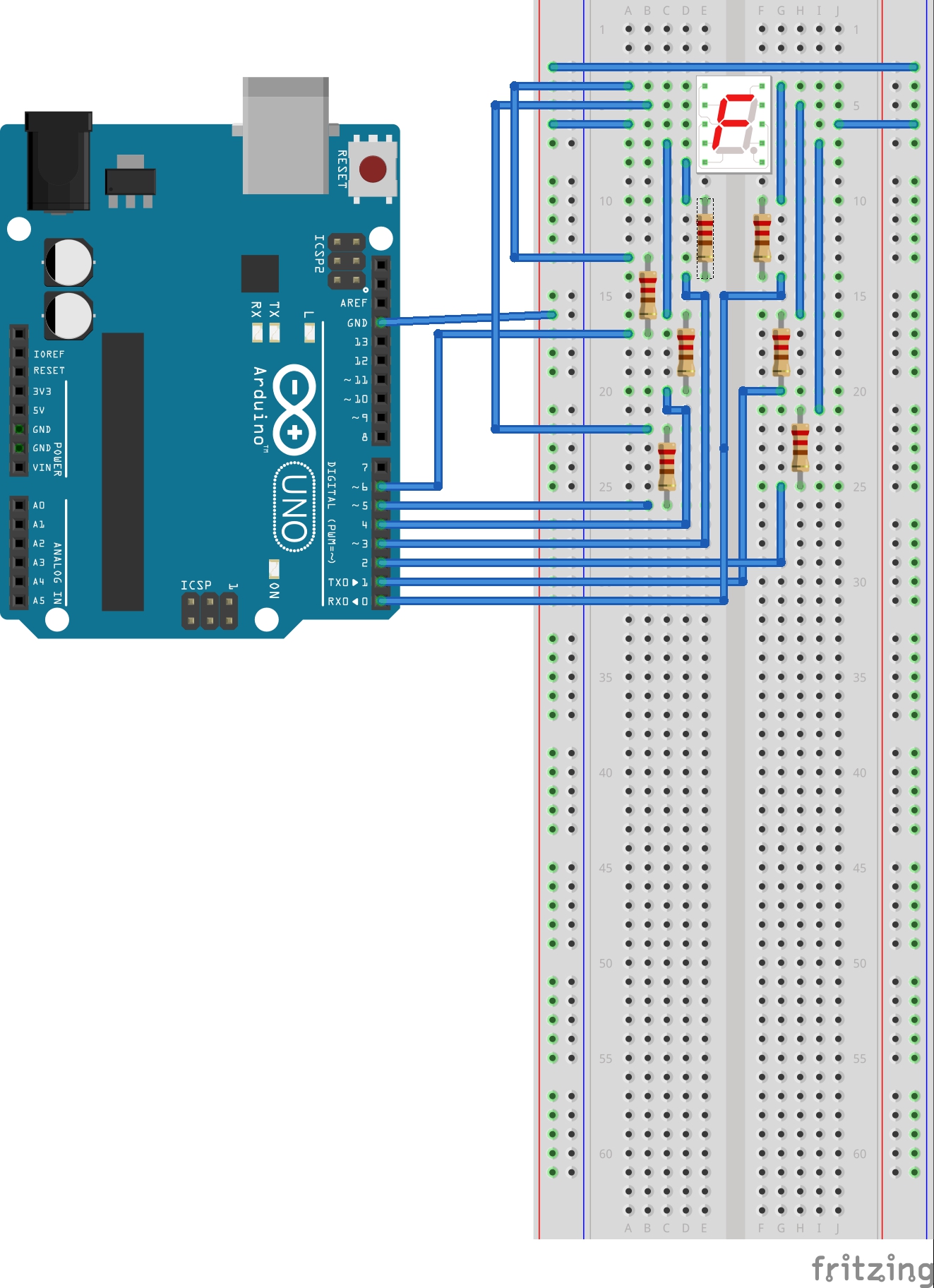
In our example we will use common cathode. This means that 7 ports/pins on the arduino will be used to connect to the 7 segments after a resistor and that ground will connect to the common cathode.
Chips exist that receive a bit pattern and then drive one or more LEDs. This will be saved for a future example.
Note: You make click on the drawing above for a larger version.
7 segment LEDs can have their pins on the sides or on top/bottom. Here is an image to help this make sense:
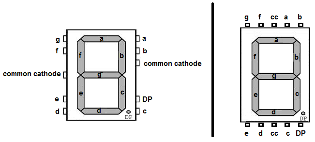
We will be using a 7 segment LED that has side pins. We will connect pins 0-6 of the arduino to pins a-g on the LED. Because the 7 segment LED (like normal LEDs) will eventually burnout when conneted directly to power (+5v), we will use a resistor to protect it.

/*
  7 Segment LED

  This example code is in the public domain.
 */

// we will use pins 0-6 to be the 7 pins of the display (ignore decimal point)

// 7 segment LED
//    a
//  f   b
//    g
//  e   c
//    d

// 0 is a b c d e f    1111110
// 1 is b c            0110000
// 2 is a b d e g      1101101
// 3 is a b c d g      1111001
// 4 is b c f g        0110011
// 5 is a c d f g      1011011
// 6 is a c d e f g    1011111
// 7 is a b c          1110000
// 8 is a b c d e f g  1111111
// 9 is a b c d f g    1111011

int digits[10] =
 {
   0b1111110,
   0b0110000,
   0b1101101,
   0b1111001,
   0b0110011,
   0b1011011,
   0b1011111,
   0b1110000,
   0b1111111,
   0b1111011
 };

int bits[7] =
 {
   0b0000001,
   0b0000010,
   0b0000100,
   0b0001000,
   0b0010000,
   0b0100000,
   0b1000000
 };

// the setup routine runs once when you press reset:
void setup()
 {
    int i;
    // initialize the digital output pins
    for (i=0; i<7; i++)
     { /* for each segment/pin */
       pinMode(i, OUTPUT);
     } /* for each segment/pin */

 }

// the loop routine runs over and over again forever:
void loop()
{
  int i;

  for (i=0; i<10; i++)
   { /* for */
     displayDigit(i);
     delay(1000);
   } /* for */
}

void displayDigit(int d)
 { /* FUNCTION displayDigit */
   int i;

   for (i=0; i<7; i++)
    { /* for */
      if (bitSet(i,d))
         digitalWrite(i, HIGH);
      else
         digitalWrite(i, LOW);
    } /* for */
 } /* FUNCTION displayDigit */

int birSet(int b, int d)
 { /* FUNCTION bitSet */
   int tmp;

   tmp = bits[b] == (bits[b] & d);
   return tmp;
 } /* FUNCTION bitSet */
Download code
[Arduino index | Modules index]