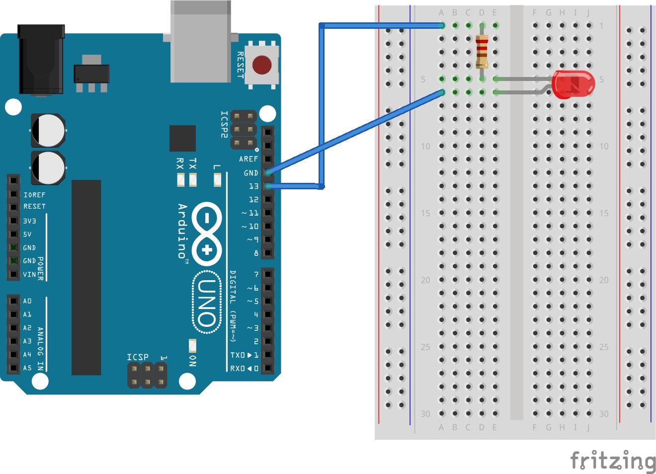
The goal of this module is to make an LED fade (go from dim to bright). You will build a circuit with a breadboard, led and a resistor that fades.
Note: You make click on the drawing above for a larger version.
LEDs are diodes. Diodes are electrical devices that only allow electricity to flow in one direction. It is very important that you orient the LED the correct way.
When connecting the LED, notice that one leg of the LED is longer than the other. The longer leg is the anode (the positive side). In the drawing the longer leg is the one with the bend in it (the lower leg in the picture above).
NOTE: Put wire in pin 11 -- not pin 13 as shown. You must use a PWM pin (a pin that will send a voltage other than 0 or 5).
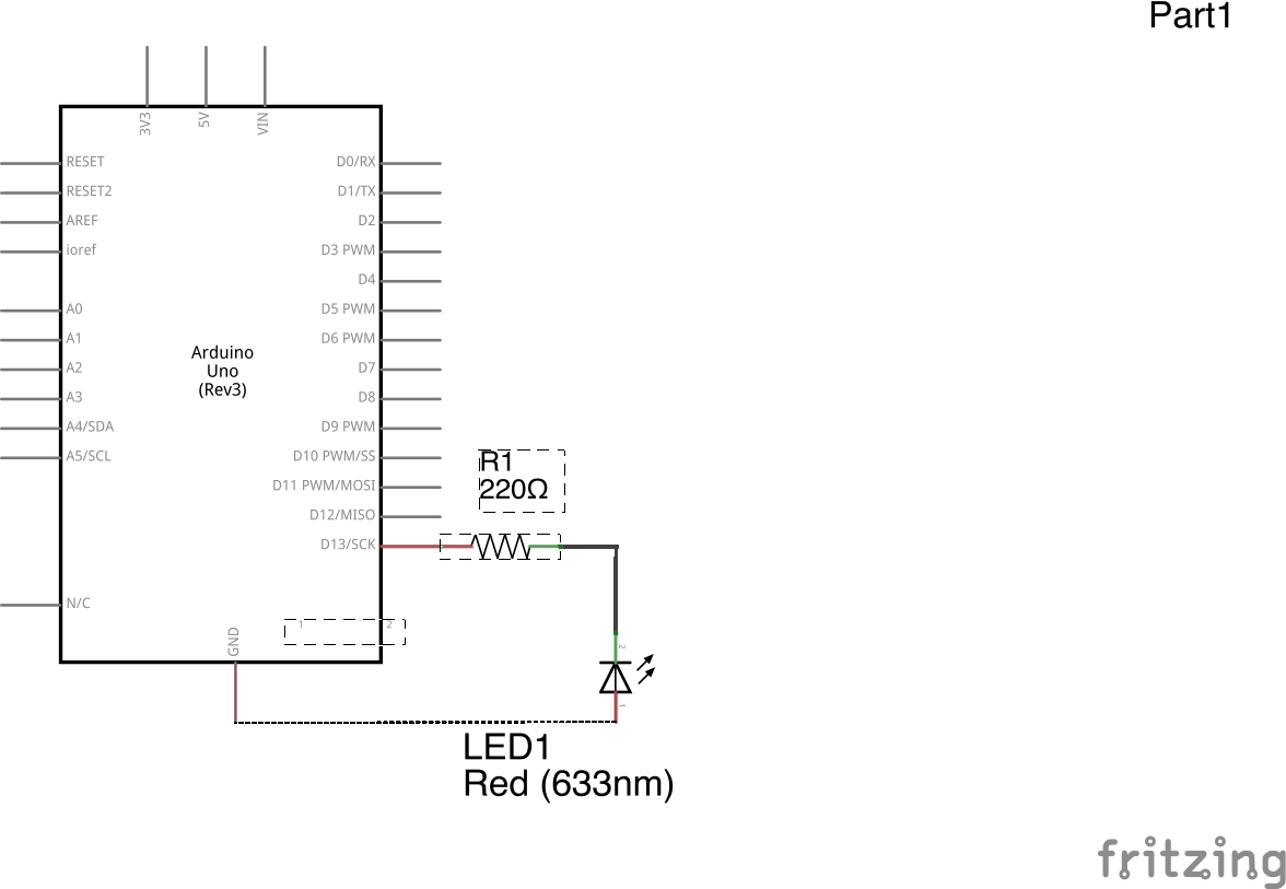
/*
 Fade

 This example shows how to fade an LED on pin 11
 using the analogWrite() function.

 This example code is in the public domain.
 */

int led = 11;          // the pin that the LED is attached to
int brightness = 0;    // how bright the LED is
int fadeAmount = 5;    // how many points to fade the LED by

// the setup routine runs once when you press reset:
void setup()  {
  // declare pin 11 to be an output:
  pinMode(led, OUTPUT);
}

// the loop routine runs over and over again forever:
void loop()  {
  // set the brightness of pin 11:
  analogWrite(led, brightness);

  // change the brightness for next time through the loop:
  brightness = brightness + fadeAmount;

  // reverse the direction of the fading at the ends of the fade:
  if (brightness == 0 || brightness == 255) {
    fadeAmount = -fadeAmount ;
  }
  // wait for 30 milliseconds to see the dimming effect
  delay(30);
}
Download code
[Arduino index | Modules index]